
Using Negative Feedback to Reverse Operation
Every engineering student is familiar with the concept of negative feedback. In electrical engineering it is a useful tool in increasing the stability of a system, increasing bandwith of the system, increase input resistance, decrease output resistance, improve noise performace etc. However there is another important application that it is used for and almost no textbook mentions it. It is a fundamental principle that some familiar circuits use but they are not presented/explained that way.
In simple terms negative feedback means anyting that reduces the effect of input to the output. Usually we are introduced with negative feedback system with the following figure.

However, not every feedback system has an obvious physical loop connecting output to the input as shown in the figure. For example the Common Source (CS) amplifier with source degeneration resistor \(R_s\) uses the negative feedback principle but there is no physical feedback loop. The resistor \(R_s\) takes the output current to build up a voltage across the resistor which reduces available input voltage \(V_{GS}\) which acts as negetive feedback.

Now going back at the basic feedback loop figure, if the forward gain \(a(s)\) is high enough the transfer function of the system is reduced to \(1/f(s)\).
\[\begin{align} x_{o} &= \frac{a(s)}{1+a(s)f(s)}x_{i} \nonumber \\ x_{o} &= \frac{1}{f(s)}x_{i} \nonumber \\ x_{i} &= f(s) x_{o} \nonumber \\ x_{i} &= F(x_{o}) \nonumber \\ x_{o} &= F^{-1}(x_{i}) \nonumber \end{align}\]The input of the feedback path is the output of the closed loop system. Hence the closed loop system is actually implementing the inverse function of the feedback path1. Explained differently, when the error \(\epsilon(s)\) is zero or close to zero the feedback path \(F(.)\) is taking \(x_{o}\) as input and producing \(x_{i}\) as output which is actually the closed loop input quantity. Effectively, the closed loop system is implementing the \(F^{-1}(.)\) function where \(F(.)\) is the feedback path function.
This is a very powerful conclusion because it lets us implement \(F^{-1}(.)\). This is important because it lets us to inverse a function even when simply forcing an exitation at the output node of a function block is physically impossible. This is the case for the transistors. The input exitation for a transistor is gate voltage and the output respose is drain current. However, it is not possible to inject current at the drain/collector and subsequently produce a voltage at the gate node \(V_{GS}\) or \(V_{be}\). (Because drain current cannot be produced without lowering the built in potential which requires gate voltage).
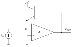
One of the most important circuit in analog design is the current mirror which converts input current to a fixed voltage (\(V_{GS}\) or \(V_{be}\)) and then converts that voltage to current effectively mirroring that current. But how do we produce a voltage from a drain current in a transistor which cannot implement this reverse function automatically? The solution is to use negative feedback and place the transistor in the feedback path2. Current is injected in the drain node. The forward gain \(a(s)\) should be high in order to perform inverse operation. For the \(a(s)\) block, the output is a voltage \(V\), the input is a current \(I\). The gain of \(a(s)\) block is \(V/I\) which is a reristance. Hence, a high resistor needs to be placed as the \(a(s)\) block. High resistance means the current through the resistor will be very small . However, there will not be any current flowing through that resistor anyway becuase the resistor is connected to gate. For that reason the effective resistance is practically infinite even if \(R=0\). Hence, a short can be used in place of the resistor.

A better explanation of why the effective resistance is infinite can be analyzed by four terminal network z-parameter. From the figure below it can be seen that if \(I_2\) is zero \(I_1\) must also be zero. There is not any path to ground for the current. Hence, regardless of the value of \(R\), the \(R_{21}\) or \(R_{12}\) is infinite.

To me it is far more insightful to know the principle behinde the operation of the circuit rather than taking the circuit as an special case for granted which does not clearify the operation. I find it very upsetting that almost no book in analog design describes this circuit this way. This priciple of using negative feedback this way led me to understand other circutis like latch and other memory circuits that use positive feedback to pull the output to one of the rail voltages.
Usually the drain node is used as input node in current to voltage conversion. But this need not be the case. We can use the souce terminal as input node as well. Here is an implementation showing that.
As this configuration needs additional transistors to make the forward gain block, this is not a popular choice for the current mirror.